tri-band mobile antennas
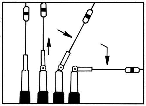

Most Comet mobile antennas over 29″ length have a fold-over hinge built into the base section of the antenna. It is NOT an automatic fold-over, you must manually lift the element up and out of the socket and lay the antenna whip down in order to enter garages, parking structures etc…
It is important that you lift the whip completely up and out of the socket before folding the hinge.
Like any hinge, it will BREAK if it is folded the wrong direction. The hinge rotates 360 deg inside the socket so it will fold in the direction needed.
Many Chinese copies and other look-a-like antennas have very annoying problems associated with their fold-over hinges. The most common is a weak spring. The antenna will lift up and out of the socket all by itself at highway speeds! The antenna is unusable when it is laying down and most users need to defeat the hinge or constantly adjust the angle to keep it vertical.
To be honest, Comet had this problem “initially” as well! The weak fold-over spring was almost always a problem with the larger antennas. Comet engineers went to work and re-designed the fold-over. Our larger antennas now have a threaded collar around the hinge: Loosen the collar, lift it up, and the hinge is exposed. No more problem of the antenna spring expanding and the antenna laying down by itself at highway speed!
**Warning** Some antenna companies have copied the Comet fold-over design and improved their fold-over feature, but many have chosen NOT to make the improvement and save the cost.
Tri-Band 6M/2M/440MHz mobile antenna, black anodized
Keep in mind the SBB15 is a 1/4 wave on the 6M band. A 1/4 wave is only half an antenna, the other half is the ground plane underneath it. Installing a 1/4 wave on 10 different vehicles will create 10 different SWR results.
The SWR on a single band antenna can be adjusted by adjusting the length of the antenna to compensate for the difference in impedance provided at each mounting location. Not so with dualband or triband antennas, the power feeding coil is pre-set at the factory.
If the SWR is elevated, adjust the antenna location until you find the the best SWR.
Gain & Wave:
50MHz: 1/4 wave
2M: 4.5dBi 6/8 wave center-loaded
440: 7.2dBi 5/8 wave x 3
VSWR: 1.5:1 or less
Max Power: 120 watts FM
Length: 61″
Connector: PL-259
Comet “locking” fold-over hinge included

SBB224NMO
Tri-Band 2M/220/440 mobile antenna
Keep in mind the SBB224 and SBB224NMO are a 1/4 wave on the 2M band. A 1/4 wave is only half an antenna, the other half is the ground plane underneath it. Installing a 1/4 wave on 10 different vehicles will create 10 different SWR results.
The SWR on a single band antenna can be adjusted by adjusting the length of the antenna to compensate for the difference in impedance provided at each mounting location. Not so with dualband or triband antennas, the power feeding coil is pre-set at the factory.
If the SWR is elevated, adjust the antenna location until you find the the best SWR.
Gain & Wave:
2M: 2.15dBi 1/4 wave
220MHz 3.5dBi 5/8 wave
440MHz 6.0dBi 5/8 wave x 2
VSWR: 1.5:1 or less
Max Power: 100 watts
Length: 36″
Connector:
SBB224 PL-259
SBB224NMO NMO Type
Fold-over hinge included